
Quick Guide PDF Download: Behringer_CT100_Cable_Tester_examples
I recently bought a Behringer CT100 cable tester. I have a lot of different audio cables, and this gizmo is great for testing whether or not there are intermittent problems (shorts or breaks). A cable that otherwise looks fine may be hiding a broken wire that works sometimes, but then cuts out during a gig. That’s a big problem.
The main issue with the tester that I’ve heard from others is the lack of clear instructions. There are at least a couple of good videos on YouTube showing the basic functions of the tester and how to connect cables. I’ll give a brief look at it here and explain how to read the results. You can download a Quick Guide PDF to take with you using the link at the top of this page.
It is a 6-in-1 tester, meaning it was designed to test 6 different kinds of cables:
- XLR [X is from the Canon X-series connectors. L is for Latch. R is for rubber-coated] This is a standard microphone cable connector.
- 1/4 inch (TS, TRS) May also work with B-gauge (tip is different shape)
- RCA (phono)
- TT (Tiny Telephone, also called Bantam TT, 4.4mm) This is most common on “patch bays” for audio gear. I don’t have any of these to test. They are similar to the TRS plugs, but with small rounded Tips and an indented Ring.
- Midi (tests 3 middle pins only)
- 1/8 inch (3.5mm)
Essentially, the tester lights up a grid of red LEDs to show if there is a good connection on each wire in the cable from one end to the other. Once connected, you can move the cables around to see if any of the “intermittent” lights come on. If they do, there is either a break in one or more wires. If more than one light per row or column lights-up, there may be wires shorting (connecting when they shouldn’t).
HOW TO USE
1. With the device off, plug each end of a cable is plugged into the device. One end always goes into an INPUT connection, and the other end always to an OUTPUT connection.
2. Turn the device on, moving the slider switch to the “cable tester” position.
3. The grid of LEDs will light up. Press the reset button to clear the “intermittent” lights and show just the ones the tester detects.
4. Interpret the results
RESULTS
There are three rows of LEDs for input and three columns of LEDs for outputs.
For most cables, you want Pin 1 on the Input to light up with Pin 1 on the Output, Pin 2 with Pin 2, Pin 3 (if it exists) with Pin 3.
A cable with 3 pins like an XLR M/F will light up diagonally like this:


For cables with only two “pins” expected, like RCA cables, it will only light two of the LEDs:
If there is a break in a wire that happens when the cable is moved, the Intermittent light should light for whichever wire it detects.
If there is a short in a wire, then more than one light will appear in a column or row (For example, if pin 1 of Input goes to pin 1 of Output, that light will turn on, but if pin 2 of the Output is also electrically connected to pin 1 of the Input, then the two right LEDs on the top row would light). Shorts are more rare than wire breaks.
HOWEVER…
The odd part of this tester is when we plug in a cable with just two “pins” into the 1/4-inch jacks or the 1/8-inch jacks. This part is not documented with the very short manual that comes with the unit, so I’m showing some pictures here of what to expect and how to interpret what you are seeing.
Many 1/4-inch and 1/8-inch cables are “mono” or “unbalanced”, also called “TS” cables. These only have a tip and a shield portion, no “ring” portion. The tester doesn’t have separate inputs for these kinds of cables, so when they are inserted into the TRS holes, the tester thinks there are pins shorted, typically pins 1 and 3, with 2 being the Tip. This causes an unusual pattern on the LEDs, however it is the correct pattern for this kind of cable on this tester.

When the cable has been wired with standard polarity (1 and 3 being joined together or shorted on the Shield, and pin 2 going to Tip), the results should look like this:
This shows Pin 1 of the input lighting up pins 1 and 3 on the output. Since they are wired together on Shield that makes sense. This is also true of Pin 3 of the Input (lights pins 1 and 3 of the output). Pin 2 (Tip) of the input lights up Pin 2 of the Output, so that is also correct.
This is the correct lighting for these correctly wired cables:
XLR to TS
TS to XLR
TS to TS (1/4 or 1/8-inch)
WHEN THINGS ARE NOT WIRED CORRECTLY
Here is an article about some cables that are inverted polarity (pin 3 as TIP instead of pin 2).
https://www.prosoundtraining.com/2010/03/11/which-pin-is-hot-and-when-does-it-matter/
I encountered such a cable today in my box ‘o cables. Here is what it looks like on the CT100. The XLR is on the output side. Pins 1 and 2 show shorted and Pin 3 is on the Tip of the input TS.
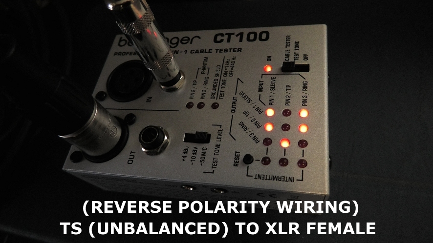
Normally it would be Pins 1 and 3 shorted and Pin 2 on tip. But this is a reverse-polarity XLR to TS cable. (I’m not sure why I even have it, but it proved handy for this blog entry).
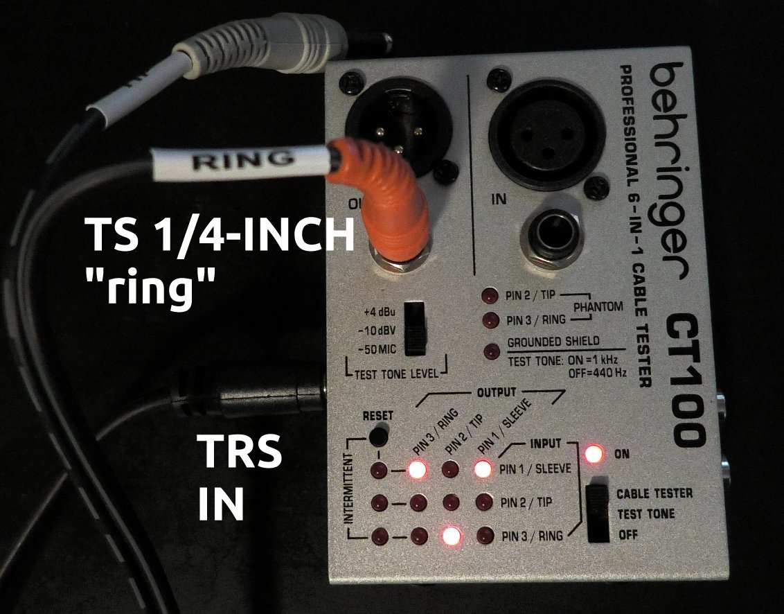
ANOTHER SPECIAL CASE: TRS TO SPLIT TS (normal polarity)
Using the Behringer CT100 cable tester with split TRS to two TS cables will give different LED patterns based on which is chosen as the input and which is the output, also depending on the type of plug.
IMPORTANT NOTE: To reduce confusion, in my example pictures below I’m using TRS 1/8-inch as the input. Even if you normally use TRS as an output, for cable testing purposes these examples will work for you. The examples will show both RCA as TS and 1/4-inch as TS. On this tester it makes a difference if you are using 1/4-inch plugs, because the 1/4 jacks on the tester are expecting to only ever have TRS plugs inserted. Thus it will always indicate that the Sleeve and Ring of the output are shorted (there is no separate Ring in TS).
The Sleeve is always shared between the three connectors, so Pin 1/Sleeve will always light LED Pin 1/Sleeve.
TRS Tip is the Tip on one of the TS connectors (sometimes color coded as white), and the TRS Ring is the Tip on the other TS connector (sometimes color coded as red). I use the memory phrase “Red is Ring” to quickly see the difference.


If I got anything way wrong, please comment.
